
- #Battery isolator relay diagram install#
- #Battery isolator relay diagram driver#
- #Battery isolator relay diagram full#
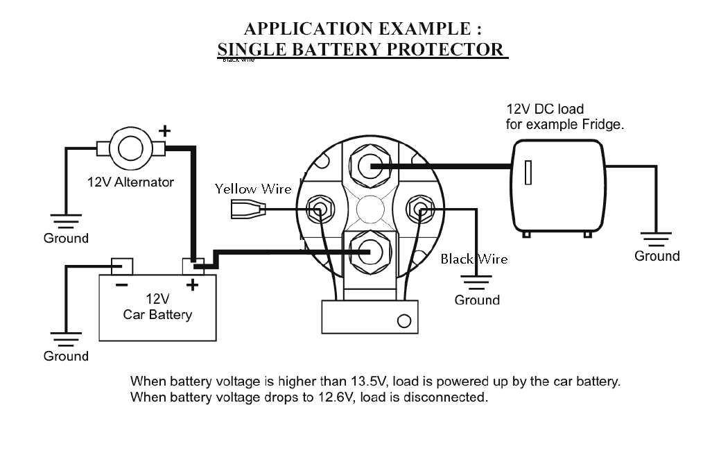
The resultant flicker of the lights will alert the driver of the system overload. When the main battery voltage rises above 13.3 volts again, the relay will again close in about 2 seconds to retry charging the auxiliary battery. This might happen when the alternator is not able to supply sufficient current to all the loads and charge the auxiliary battery. If the voltage should drop below 12.0 volts for more than two seconds while the engine is running, the relay will drop out. When the ignition switch is turned off, the relay will open immediately. When this voltage goes above 13.3 volts for approximately 12 seconds, as happens when the engine is running normally (normal alternator output voltage is approximately 14.4 volts), it will close the isolator relay providing charging current to the auxiliary battery. It operates by sensing the voltage on the main 12 volt system. There are three (3) wires to connect to the delay unit: one from an ignition switched 12 volt source, a ground and the isolator relay coil. Additional relay under the driver’s seat. Fuse and relay holder D under driver’s seat -SD. It operates in combination with a conventional continuous duty cycle isolator relay that has been used by a number of vehicle manufacturers. The following blocks are provided in Volkswagen Crafter: Power supply fuse, cl. The unit is fully encapsulated in a plastic enclosure for mounting in the engine compartment with two screws. This allows the use of self-exciting alternators and lets the engine briefly warm up prior to placing the load of a heavily discharged auxiliary battery on the alternator. Unlike diode isolators, this system provides an engine driven alternator with main battery before connecting the auxiliary battery.

Intellitec’s Battery Isolator Relay Delay offers a low cost, reliable approach to charging multiple batteries. It works great and I don't have to remember to turn a switch and it doesn't allow my alternator to be over worked.Intellitec Isolator Relay Delay 00-00629-120 It is very small unit and marine approved so it can handle moisture and vibration. When I shut outboard off as soon as the voltage drops to 12.8 volts the isolator disconnects the two batteries.

#Battery isolator relay diagram full#
When I start my outboard the isolator allows starter battery to reach full charge 13.3 volts before it connect second battery for charging. Also connected the isolator and both batteries to a common ground and it was finished. Simply mounted in next to my starter battery ran a cable from the start battery positive terminal to the isolator terminal "A" then another cable from isolator terminal "B" to the second battery. The nice thing is that I didn't have to connect it to the alternator or the ignition. Battery Guard® 1000 Battery Guard 1000® RV-C Battery Guard® 2000 Battery Guard® 3000 Lift Gate Battery Guard® Isolator Relay Delay Battery Isolator Controller BiDirectional Isolator Relay Delay (B.I.R.D.®) Bi-Directional Isolator Relay Delay Bi-Directional Isolator Relay Delay Gas Bi-Directional Isolator Relay Delay. It is completely automatic and isolates the battery when a charging source isn't available. They were a little higher priced so I shopped around and found it on craigslist.
#Battery isolator relay diagram install#
Simplest install available and I bought it online just google it or you can find it on the DIY website. Very simple solution that I used is an AOPEC Smart Battery Isolator.


 0 kommentar(er)
